Table Drawings#
Table drawings are used for documents where, for some reason, table borders are absent. These can be foreign documents (for example, Invoice), where table lines are not provided. They can also be Russian documents where the table lines are partially not drawn (missing interline lines).
.png)
Working with the "Table Drawings" setting is demonstrated here.
Main tools for working with table drawings:
.png)
| No. | Tool | Description |
| 1. | button  | Allows you to add a table drawing. |
| 2. | button  | Allows you to delete a table drawing. |
| 3. | button  | Allows you to add a column binding. |
| 4. | button  | Allows you to delete a column binding. |
| 5. | button .png) | Allows you to add column width. |
On the right side of the workspace panel, all parameters are displayed that allow you to configure the table drawing.
Properties and tools for working with table drawings:
.png)
| No. | Property/Tool | Description |
| 1. | Description | Description of the table drawing. |
| 2. | Top Left Corner | Anchor binding of the top left corner. |
| 3. | Top Right Corner | Anchor binding of the top right corner. |
| 4. | Bottom Right Corner | Anchor binding of the bottom right corner. |
| 5. | Bottom Left Corner | Anchor binding of the bottom left corner. |
| 6. | Top Table Limit | Table limit from the top of the page. You can specify values in pixels or percentage using the symbol |
| 7. | Bottom Table Limit | Table limit from the bottom of the page. You can specify values in pixels or percentage using the symbol |
| 8. | Columns | Anchor bindings for columns. |
| 9. | Column Widths | Widths of the columns. You can specify a fixed value or a percentage of the total table width in the format If the sum of the percentage values of all specified columns is equal to or greater than |
| 10. | Filter Columns | When this setting is enabled, only those lines that are drawn in the table drawings will be considered for table recognition. |
| 11. | Filter Rows | When this setting is enabled, only those lines that are drawn in the table drawing will be considered for table recognition. |
| 12. | Display Borders | Control the display of the table drawing borders. |
| 13. | Border Thickness | Thickness of the table border in pixels. |
| 14. | Border Color | Color of the table border in RGB format. For example, #000000 — black, #FF0000 — red. |
| 15. | Column Framing | When this setting is enabled, column lines are displayed on the table drawing. |
| 16. | Row Framing | When this setting is enabled, row lines are displayed on the table drawing. |
| 17. | Header Framing | When this setting is enabled, the first row is displayed on the page drawing. |
| 18. | Columns for Row Definition | Indices of the columns by which rows will be defined. If the value is empty, all columns will be included. The index starts from 0. |
| 19. | Horizontal Line Binding | Parameter for binding the horizontal line. Possible values:
|
| 20. | Horizontal Line Offset | Offset of the horizontal line along the Y-axis in pixels. For precise offset, values should be specified in the format |
| 21. | Search Criterion for Horizontal Lines | Offset of text blocks to determine their intersection. By default, the value is |
| 22. | Stretch Table | When this setting is enabled, the table drawing will stretch to the following pages. This parameter is necessary if the table headers are only on the first page. |
To bind the table borders for each corner of the drawing, it is necessary to specify an Anchor and set the parameters for the position of the lines relative to the selected Anchor.
Parameters for the anchor bindings of the table corners:
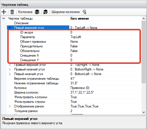
| No. | Parameter | Description |
| 1. | Anchor ID | ID of the Anchor to which the binding occurs. |
| 2. | Parameter | Binding parameter. Possible values:
|
| 3. | Binding Object | Point or edge of the Attribute area for binding the selected parameter. |
| 4. | Forced | When this setting is enabled, the specified Anchor parameter will be forcibly set to the selected binding object without checks. |
| 5. | Mandatory | When this setting is enabled, an error in this binding will be considered a failure to find the entire element. |
| 6. | X Offset | Offset along the X-axis in pixels. For precise offset, values should be specified in the format This setting is used when a character (parenthesis or colon) is specified after the Anchor that should not fall into the Attribute area. |
| 7. | Y Offset | Offset along the Y-axis in pixels. For precise offset, values should be specified in the format + -. For example, +10-20. |
To display the borders of the table drawing, it is necessary to set the display parameters for each of the borders.
Parameters for displaying the borders of the table drawing:
.png)
| No. | Parameter | Description |
| 1. | Left Border | Display of the left border of the table drawing. |
| 2. | Top Border | Display of the top border of the table drawing. |
| 3. | Right Border | Display of the right border of the table drawing. |
| 4. | Bottom Border | Display of the bottom border of the table drawing. |